Next Passion
Info on building of the next Passion
Monday was the coldest Australia Day in Sydney for 50 years and the cold and wet has continued thwarting my plans to start skinning the hull. In the forced lull I have fitted four of the six locker shelves in the quarter berth. If the wet persists I will adjust the frame support and complete the last two shelves and perhaps the locker fronts as well.
Plan B for an extended wet period is to complete the shelves in the saloon. I have already completed the shelves either side of the chainplate supports so there are four more shelves that could be installed and I and can complete the locker fronts if I get desperate for jobs.
The tarpaulins are doing a great job of keeping the hull dry and the underside of the cockpit is proving to be a great workbench. It is reinforced with 450 grams per m^2 of biaxial glass in West epoxy so the plywood is well protected.

Fitting quarter berth shelves is an ideal wet weather task.

The underside of the cockpit has proved to be a great workbench.
Before I start fixing the plywood skin to the hull I am completing all the blocking that goes from under the keel frames to the plywood inside face. Each layer of blocking can be fitted and pressed into place in a bed of epoxy resin like a tile in a mosaic. Once all the blocks are in place the surface will be planed so that the plywood can be glued direct to the underside of the frame. The central layer of the blocking has only to resist the shear stress in bending and as it is on the neutral axis this is where 30 mm square access holes are located to carry all the water services and bilge pump plumbing. The bottom most layer of blocking is against the hull and is continuous except for the limber holes needed against the keel and stringers. Against the keel directly above the limber holes the frame section is 110 mm wide, 80 mm deep and encased in 2 mm thick high strength epoxy glass so it is a very impressive structure. Two stingers run through the blocking area on each side so there are between 8 and 12 blocks per layer for each of the seven frames. It is quiet time consuming to shape the blocks to transition smoothly from the 80 mm wide sections to the 110 mm wide section between the keel and king plank but a good smooth transition is needed so that the glass cladding is well bedded down for maximum strength. I have calculated that in the keel frames and blocking there is 224 individual pieces varying from metre long 80 mm wide by 6 mm deep layers in the frames to tiny pieces with two 45 degree angles. As a result of this time consuming task progress looks slow but it will pay dividend minimising the time for completion after the hull is turned. If I have counted correctly I have just 28 little pieces to cut and fit before I can start fairing the section in preparation for the skin.

Near side frame with 30 mm access holes through the neutral axis and far side frame with the extra layer of blocking spanning the access holes
During the hot days last week I left a few projects for the wet days so a little work was done under the new tarpaulin. The cleats for the quarter berth plywood bunk bases are all but completed and if the wet weather continues I might also install some shelves in this area. The wet time has also been used to plan the location of all the electrical circuits, light fittings and water services. There are little bits of masking tape all over the bulkheads with little hieroglyphics which meant something when I scrawled them. With more rain forecast this week I am going shopping for some serious bits like the rudder stock and prop shaft so that I can get these aligned while I can still get a laser line through the hull.

Another tarpaulin to keep the hull dry
The photo with the new tarpaulin stretched over the hull gives a good idea of what the finished product will look like. The piece of plywood sitting under the tarp at the stern does spoil the smooth lines but it is needed to bridge the gap between the transom and the aft perpendicular because there is no keel in this area and without the ply the tarp sags and fills with rain water.
Externally it seems no progress has been made on my Didi 40cr but behind the scenes little steps have been made. The underside of the cockpit floor is all but completed. Where the top of the rudder post is mounted all the reinforcement is in place, nicely routered with 6mm radius corners and double coated with epoxy resin. The corners that are not secured with cleats are double taped with epoxy fibreglass, sanded back and top coated with clear epoxy so that section of the yacht is finished.

Completed rudder post top support structure
Under the forward part of the cockpit where it is 850 mm wide the glass reinforcement has been sanded and primed with a first coat of Interguard. This is a good place to practice getting a good finish on the glass covered plywood. Despite the use of peel ply over the glass the finish is not as flat as I expected so I need practice spreading the epoxy with a fine nap roller to minimise the amount of filler required for the production boat standard I am trying to achieve.

First coat of Intergard primer on the cockpit underside
Elsewhere the inside of the water tanks have been lined with a light woven glass cloth had double coated with epoxy resin. Once the skin is on the hull that surface of the water tank will be lined from the access hatches in the top. It will be tight work but at least it will be downhand.
One of the next steps is to cut all the access ways for the electrical cables, water pipes and engine services. I want to do this while I have good access to the bulkheads and before the skin is started.
Sad day in Sydney with the hostage drama and the loss of two great lives. It is hard to be cheerful when there is so much sorrow but I battled on with the four sheets of plywood that would finish off the cockpit. First I had to cut dress fit and install some floor bearers for the 1.6 metre wide aft section. While the glue was curing I cut the four panels and fitted and installed them progressively. It was a big glue day with some long and wide gluing surfaces which required a big batch of glue. In the heat it was a battle to spread the glue before the mass in the glue pot heated up and accelerated the set time. To keep the glue time short each panel was pre drilled and temporary supports places so that the panel could be placed promptly. The process worked well but it was a long day and well after six when I downed tools happy with the effort.

Didi 40cr wide stern racing cockpit fitted and glued in place
The photo shows the 850 mm wide fore cockpit and the 1.6 metre wide aft cockpit which gives a lot of room for a racing crew. Next job is to router the edges of the underside of the cockpit and glass the underside. I am going to glass both sided of the cockpit floor for in the front section to avoid the need for deck beams that would protrude into the quarter berth space. Instead the underside or the cockpit floor will be smooth. The join in the two sections is a butt join staggered so that the join is not in line with the frame. Once the hull is right way up the join will be ground back and glassed for a strong durable join.
Progress on installing the cockpit of my Didi 40cr is going well. The plan is to complete the cockpit while the hull is still upside down so that I can router the edges and glass the seams while working down hand. In Duldey’s 40cr design one side of the cockpit is a 12 mm thick plywood panel which goes all the way from the deck to the hull forming one side of the huge quarter berth in the process. To make it even more robust on one side is a wet locker which stiffens it up vertically and provides support for the front end of the cockpit which hangs in mid air on the other side. Well it does not really hang in mid air but one side of the cockpit is supported from the deck which is not installed yet so I will install a temporary strut in the quarter berth to keep it all steady until the hull is turned and the deck completed.

Didi 40cr cockpit sides being installed in the up side down hull
My Didi 40cr has a wide stern that Dudley has drawn for me and that allows an extra 250mm of cockpit width. It means the quarter berth is 125 mm wider and the locker correspondingly slimmer. It is a much more complicated structure as behind the last frame my cockpit widens out to almost 1.6 metres for a more racing oriented layout. All this discussion is to explain why there is a 45 degree corner on the front of the cockpit and not the standard 90 degree one. Tomorrow I will try to fit the floor in the front half of the cockpit and start the wide section at the back. The first part will be easy as the 12 mm plywood cockpit floor will fit on the 30 mm triangle cleats and just be slid through the 12 mm gap on the frame into the aft section where it will be joined to the 1.6 metre wide section of the floor.

Didi 40cr cockpit sides from the stern showing the cleats on the last frame ready to take the wide floor section
This photo shows the wide aft cockpit section with the sides sloping up to match the angle of the cockpit coamings. It will look very modern.
So tomorrows job is just four bits of plywood, 850 mm wide front cockpit floor, 1.6 metre wide aft cockpit floor and two aft cockpit sides.
Last night the thunderstorms stayed away and we managed a race despite the wet conditions. Racing conditions were truly tricky. Our notable win was a 45 degree lift along the Birchgrove shore that let us clear Long Nose in a single board. Our notable loss was the knock along Snail Bay on the way home where we were trapped between a Black fleet yacht stalled head to wind on the concrete dolphin and a procession of Green fleet starboard tackers coming up with breeze. A couple of tacks here in little breeze and the fleet leaders were gone. It also allowed French Connection to catch us and while we were ahead going into Humbug a big lift for the following yachts did us no good as we had to tack away from the shore on a big header.
Next week it will be fine for the Christmas Party after the race. The forecast says so and I believe it. After all the rain we have had there can be not much left. I want it to be fine for the party and I want the sun to come out so I can get on with the boat building. Today I invested in another tarpaulin to give the hull a double cover and used the time to measure up and cut panels for the cockpit. If the sun comes out I might make some progress.
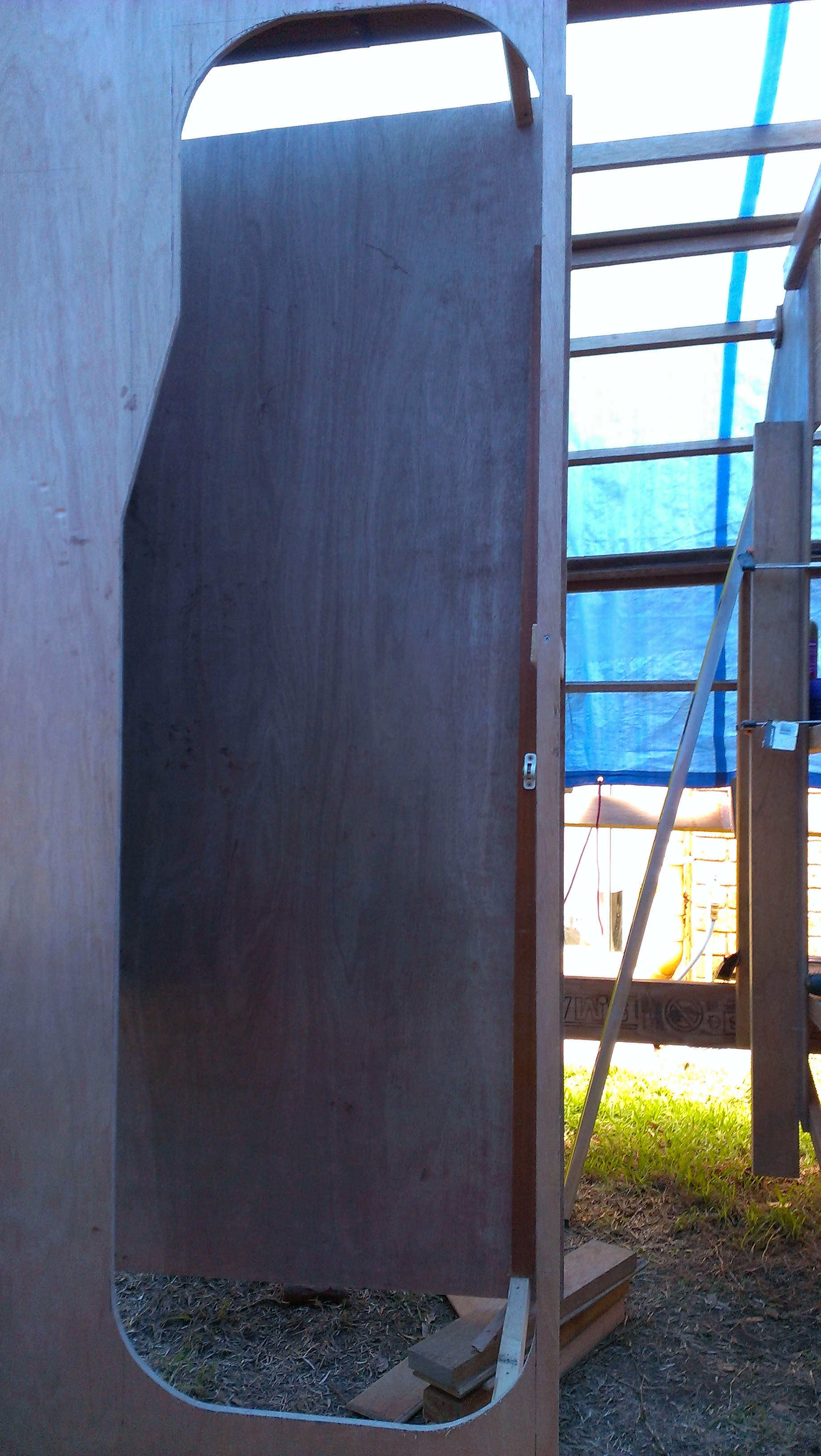
Quarter berth doorway from inside the berth. The taper matches the angle of the companionway steps so we get a bit more with for the upper body.

the finished keel king plank with the hull under covers from Sydney’s thunderstorms
I am forming up the companionway, the quarter berth cabin and the toilet and shower room. As the big flat sheets of plywood are fitted at right angles to the bulkhead this is the time to check the bulkhead alignments and stiffen up any wobbly plywood frames. Because the cleats for the enclosures are already fitted to the bulkheads progress is quite swift and with a bit of luck the two enclosures will be completed tomorrow.
The king plank looks neater with all the clamps removed. The hull is under covers to protect it from Sydney’s thunderstorms. A big one came through Wednesday night causing our twilight race at GFS to be cancelled. Nice BBQ though and the best non sailing of the week.

The seat sides connect to the keel floors to spread the keel loads
I have started work on the two 300 litre fresh water tanks on my Didi 40cr. This is twice the drinking water storage as we have on Passion and most of the time I carry just 40 litres, filling the tanks only for our cruising jaunts. Even the Beneteau 50 we chartered in the Whitsundays 14 years ago had only 1000 litres storage for six people so our 600 litres will be luxury for two.
The tanks form a for and aft structural member to share the keel loads amongst all the frames and they are the seats in the dinette. The photo shows the access holes in the top of the seats which are needed so that the skin side of the tanks can be coated with epoxy glass. The seat side faces will be glasses before the hull is skinned. The tank top on the left is glued in while the one on the right is sitting in loose in slots I installed to hold the panels for fitting and gluing. You can see the gap between the side and top where it will be glued and nailed later. Almost all the shelves have slots so that the shelves can be slipped into place.
It has taken a while but now that the frames are glassed ready for installation in the hull I am satisfied with the result.

Keel frame top webs with 2mm of epoxy glass covering.
The photo shows the frames with the doubling blocks which compensate for wood lost to the keel bolts already bonded to the laminated beams and covered with 2 mm of epoxy glass laminate. The glass content is 2000 grams per m2 and will add strength as well as protecting the timber. Across the keel the section is 110 mm wide because I have made wider frames and increased the thickness of the doubling blocks to allow for 25mm keel bolts. It is a lot of work and not required for the standard design but then I do like strong yachts.
Readers of my Passion blog will know that I put three extra 80 mm wide by 160 mm deep keel floors and two extra keel bolts in my Jeanneau SO 37 to ensure a long trouble free life.
I should stop referring to the laminated floors as keel frames because they are just the top web of a compound beam made up of the laminated floors, the spacers between the frames and the hull and the plywood cover on the outside of the hull. It is like an I beam with the hull side section a piece of plywood equal in width to the frame spacing. In my case I am adding all that glass to the top web and will be adding glass to the outside of the plywood where it will give the most contribution to structural strength. There will be glass in the bilge to hold everything together and keep out the water but I have not included that in my considerations of the strength of the frames.

Keel frames with the top web half glassed
There has not been much action on the boat building front due to a trip to Perth and three scheduled sailing days since then. It took longer than expected to glue the doubling blocks to the middle of the keel frames and router the edges of the completed units. It also took longer than expected to lay up the first three layers of 495 gram unidirectional glass on the top web of the frame. That is the stage of the photo below. Since then I have added a further two layers to get my target 2 mm of high strength epoxy glass. I estimate the design strength for the unidirectional laminate to be 300 MPa or about six times the strength of the wood onto which it is bonded. Conceptually the 2 mm of very high strength epoxy glass is in tension equivalent to 12 mm of timber which would give a similar strength to a 60 mm frame compared to the 48 mm design. It is not quite the same as the extra depth of 12 mm timber would give different area moments to resist the keel but it is pretty close. Just to be conservative I have assumed a design strength of 150 MPa and I have topped off the five layers of unidirectional with a layer of biaxial under the keelson because once the keelson goes on there is no further opportunity to reinforce the frames. All this glassing is a lot of work and messy work at that but we are installing a deeper keel to improve the windward performance with more righting moment and more lift.

Seven Keel frames fitted to the hull.

6 mm pilot holes have been drilled through the keel and frames
Today I fitted the keel frames to the hull of my Didi 40 Cr to check that they were all true. In the process I drilled pilot holes for the keel bolts to ensure that they are in the middle of the frame. Now that the fitting is complete the frames have to be returned to the workshop to have the doublers added to the front face and to be reinforced with glass. Only then will I be able to fit them permanently in the hull.

Seven keel floors ready for cleaning and dressing.

Fibreglass cheaper by the rolls
The last two days since clamping up the seventh floor frame have been spent buying glass cloth for reinforcing the top of the frames and in cutting out and routering the edges of the 100 mm ply doublers. Buying the glass from Nuplex was the easy task and by buying by the roll I have enough for the hull outside and inside. As well I have purchased the unidirectional glass for the keel floor tops and the first layer on the skin under the keel floor area. The more difficult task was buying a route table and finding a suitable router for it. Eventually I adapted an old Ryobi router to the Ozito router table by drilling the Ozito base plate to suit the Ryobi and that has worked fine. The shopping time has eaten into boat building time so this afternoon I moved into production mode. By nightfall I had routered all the ply doublers and ground all the surplus epoxy off seven frames.

Seven curves tangent to the constant V bottom section which define the keel frames shape
The last keel frame is glued up on the garage floor. It will sit half way between D and E frames and is in line with the chain plates. It is the forward most station that has a radius or 800 mm to the outside of the hull and by gluing it up on a lofted set of blocks the design hull shape should be maintained.
To show the family of curves I highlighted the lines scribed on the floor for the photo.
The longest keel frame was laminated on the garage floor today. This is the aft most frame and has no keel bolts through it but it does share grounding loads. Grounding loads are those extreme forces generated when you are flying along at eight knots and hit an immovable reef. The rear frame structure has to be strong enough to stop the back of the keel breaking the backbone. There are three frames sharing these grounding loads and they are all tied together fore and aft with a keelson structure and with the sides of the engine bearers. As a bonus there is a big frame that forms the front of the galley and engine housing and that is right above the aft end of the keel. By my calculations if we hit a reef all that will happen is the bow will dive down while the stern rises up and the water will act as a shock absorber. There are two more frame so do but these are the two shortest ones at the front of the keel so just two more days work to finish all seven frames.

The longest keel frame that will support the engine bearers.