Next Passion
Info on building of the next Passion
I took the risk that the thunderstorms forecast would not hit our building site until after the grey two pack polyurethane topcoat was sufficiently cured. The first coat had already been sanded back to remove runs and insects so all I had to do was a final wipe clean and apply the last topcoat. It was a warm day so the paint was touch dry pretty quickly but a couple of drops of rain did fall from one passing cloud and put a dot on the paint. There was nothing I could do but dab the couple of drops off the surface, remove the masking tape and go away for a coffee. The masking tape came away from the hull leaving a very crisp line and the coffee was a good mid morning pick me up. There were a few spits of rain in the afternoon so I worked away on the chart table and electrical control panel area. After a lot of procrastination I finally drew up my electrical panel. Today I cut it out from 6 mm plywood. It is certainly a lot easier to fit without the deck in place so by tonight I had it fitted and the cleat for the panel hinges epoxied in place. The painting of the keel is finished up to the stage where I need to do the filling and fairing. As I mentioned in a previous post the heat distortion from the lead filling was more than I expected but after a little filling it will be a very fair keel. Looking back to where we were twelve months ago I was laminating up the last of the keel floors prior to adding the cross keel reinforcing pieces.

The Didi 40 Cr boot top stripe with the masking tape removed
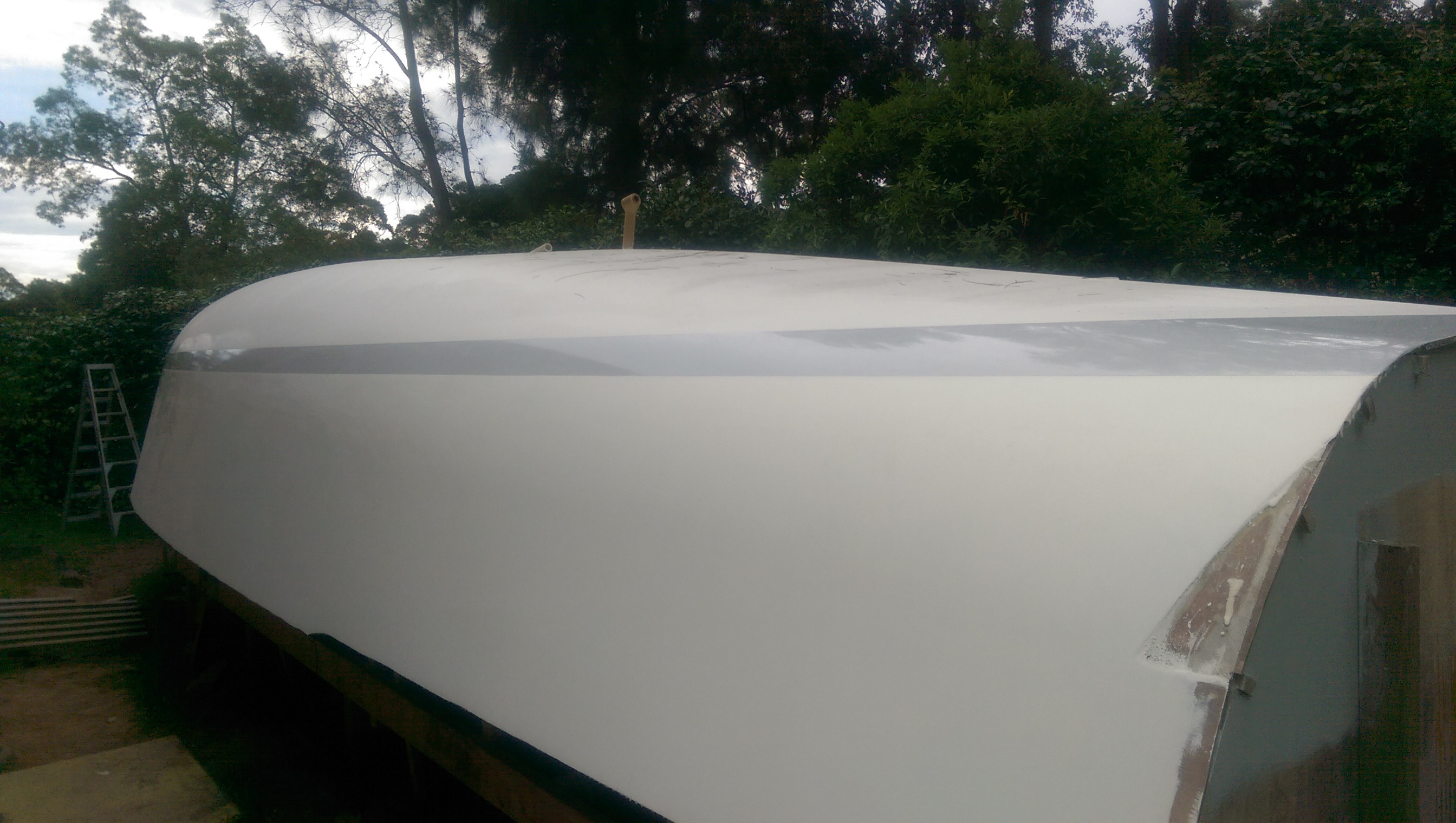
Stern view of the grey boot top stripe on our Didi 40 Cr
The primed keel for our Didi 40 Cr ready for epoxy filling and fairing

Flashback to a year ago when I was laminating the last of the keel floors

The first coat of grey paint on the boot top stripe of our Didi 40 Cr

A view of the wide boot top stripe on the stern of our Didi 40 Cr

Installing the chart table timber on our Didi 40 Cr
Dodging the weather systems coming through Sydney I have managed two undercoats and one grey top coat on the boot top stripe on our Didi 40 Cr. The boot top stripe is a small area where I can practice my painting skills. One more coat of grey and I will be able to remove the blue masking tape.
Under the hull I have installed some of the chart table structure. Dudley has sloping top on the standard design but I will have a flat top with a rail around the edges. We usually leave our sailing instructions and course maps on the chart table and they stay in place better with a flat top and rails.

Galley framing completed. Now for the epoxy fillets and ice box foam.

Starting the instrument panel and electrical board.
Humid weather with threatening clouds drove me away from the two pack polyurethane boot top painting. Under the hull the galley structure has progressed to the point where the stove recess and the ice box recess are completed as far as I can go for now. I need access to the hull for more epoxy fillets on the frames and shelves and for installing the foam for the ice box.
On the other side of the hull I have started framing up the chart table area. I want to get to the stage where I have the instrument and electrical panels framed and can measure up the hinged panel fronts.
With blue masking tape used to define the area of the boot top on our Didi 40 Cr hull looks flash. The boot top will be painted a light grey and will separate the white top side from off white antifouling.

Bow view of our Didi 40 Cr with blue masking tape defining the area to be painted light grey

Side view of our Didi 40 Cr with the boot top area masked off with blue tape
I was happy for a couple of rainy days which were good for the garden and it gave me a rest from sanding and painting. Under the protection of the hull cleats have been added to the quarter berth shelves and a frame and shelf have been cut for the galley structure. I have also made a mock up of the fuel tank out of old water proof plywood which has been in the shed for fifteen years. I thought the mock up of the tank would be good insurance to check that the tank when made from stainless steel could be fitted into the space through the locker hatch.
Fine weather returned today so I could complete the last coat of primer and in the dark of night mark the boot top using the laser level. You can just see the laser line on the hull in the photo. Two lines were needed each side to mark the top and bottom of the boot top. Dudley Dix’s plans for the Didi 40 Cr call for a 100 mm wide boot top and it looks good on the half model that Bill Bollard made for me so I will stick to that.

A plywood mock up of the stainless steel fuel tank

Using the laser level to mark the top of the boot top of our Didi 40 Cr
While sanding the flat sections of the Didi 40 Cr is pretty easy it is more difficult to get a really fair surface on the curved radius chine so I made up a torture board to the curve of the radius chine. Using a 12 mm ply off cut from one of the frames I attached a 3 mm ply panel the size of a sanding sheet with glue and silicon bronze nails. Being a hot day the fast cure West epoxy was cured in a couple of hours and I attached the 80 grit paper with Sika high strength spray contact adhesive. All that was done between morning tea and lunch.
A big advantage of the radius chine construction is that about three quarters of the length of the chine is a constant 800 mm radius so the curved torture board can be used to good effect along a lot of the hull. The hard backing to the middle of the torture board is very effective in taking off the high spots where layers of paint have overlapped.

The curved torture board sitting on the radius chine of our Didi 40 Cr

The curved face of the torture board. Not perfect but very effective

Our Didi 40 cr hull post curved torture board and washing the dust down with the garden hose.
Monday and Tuesday this week were ideal for sanding and painting but they were two of the hottest October days on record so it was tough going in the sun. The warm conditions were ideal for applying the International Interprotect over the Microsurface and by Tuesday evening I had two coats over all and a third started on the starboard bow section. I have to sand the second coat of Interprotect and apply a third and that will be it until the hull is turned and the deck installed.
I had thoughts of applying the antifouling while the hull was upside down but the Ultra I intend to use has only a two month window from application to launching so I will leave it until last. I did buy the Perfection undercoat and top coat to do the boot top line so that will give me a little stripe of finished surface along the hull to see if the finish will be satisfactory.
Today was more or less a rest day after the two big days earlier in the week and the late night last night after putting Passion back on the mooring after the twilight race. I used the time to work out where to put the fuel tank, buy some more paint and also the DC circuit board.

The bow of our Didi 40 Cr with three coats of Interprotect over the Microsurfacer. Only one more primer, two undercoats and two top coats to go.

Two coats of International Microsurface on the radius chine of our Didi 40 Cr
The weather in Sydney has turned for the better with sunny days letting me get on with the sanding and painting. I bought 20 litres of International Microsurfacer to do the final fairing over several primer coats of International Interprotect . The Microsurfacer fills the last 1mm of variations in the hull finish. It is a high build coating which is easy to sand while it is fresh but it does cure to a strong coating. So the last few days have been spent sanding all the gloss off the primer, applying Microsurfacer and then next morning torture boarding the surface ready for the next application. In under four hours I could sand the whole radius chine section of the hull from end to end. Two full coats on the radius chine and a light coat on the topsides has used most of the Microsurfacer so it won’t be long before I will be applying the final three coats of Interprotect. Because I am building in a suburban back yard I did not want to spray the Microsurfacer and roller application followed immediately by brushing off with a foam brush worked very well. The roller alone or brushing was not satisfactory but the laying off of the roller surface with the foam brush produced a much flatter surface than rolling alone. The one light coat of Microsurfacer on the top sides will make the final torture boarding a little easier and most of the coating will end up as dust on the ground. I have sanded half of the port side topsides and am delighted with the finish. In the photo the Microsurfacer on the radius chine has still to be sanded but the topside on the front half has been sanded ready for more layers of Interprotect.
The aluminium angle sitting on the hull is what I am using as a guide for the sanding. The torture board is not long enough to get a fair shape over a long section but a combination of the checking with the aluminium angle and sanding with the torture board is working well.
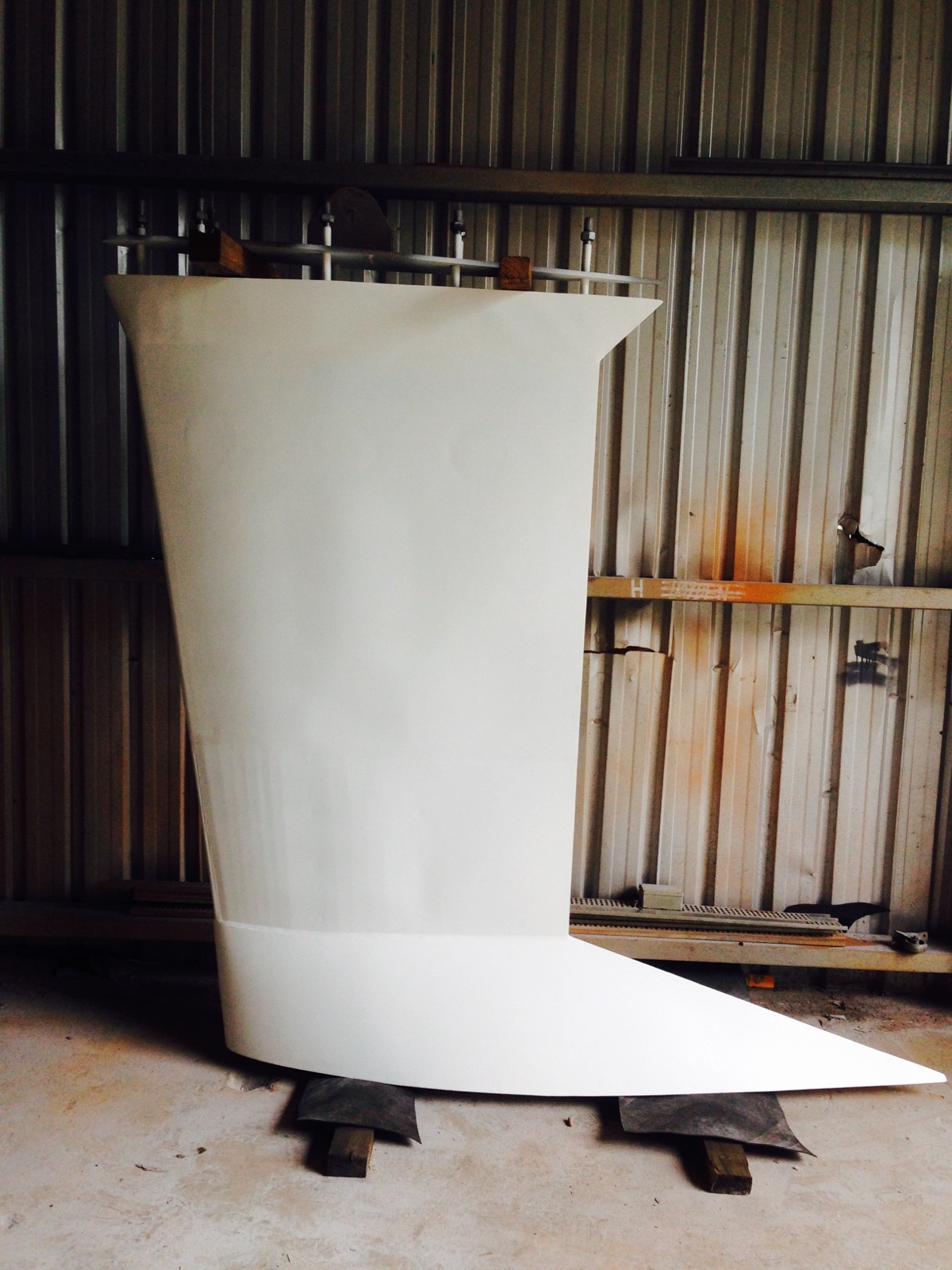
Today was the first chance I had to see the keel now that the foundry has added the last 650 kg of lead to the fin section. I calculated out the amount to go in each of the three chambers and the foundry batched each load separately. I was a little out with the estimates and the last few kg were added to the central chamber. The benefit of large pour is that each lead section is structurally sound while the downside was a slight bulging of the walls between the vertical pipe stiffeners due to the heat. With a little filling and fairing we will have a good finish.
The yellow lines on the side of the fin show the level of the lead. From the lines down to the base it is 1650 kg of solid lead.
The Didi 40 Cr fabricated steel lead filled keel. The two yellow lines on the side show the level of the lead so the centre of gravity of the keel is nice and low.
In preparation for installing the settee backs that form the box structure supporting the chainplates I am painting inside the shelves and the back of the plywood front. These are small shelves with just a 150 mm wide opening so to paint them after assembly would be quite difficult. I have used three coats of Interprotect two pack epoxy primer for the inside of the shelves. On the settee backs I masked off the area which will be glued to the frames and shelf front cleats and you can see from the photo of the inside face of the settee backs that there is a large gluing surface area.
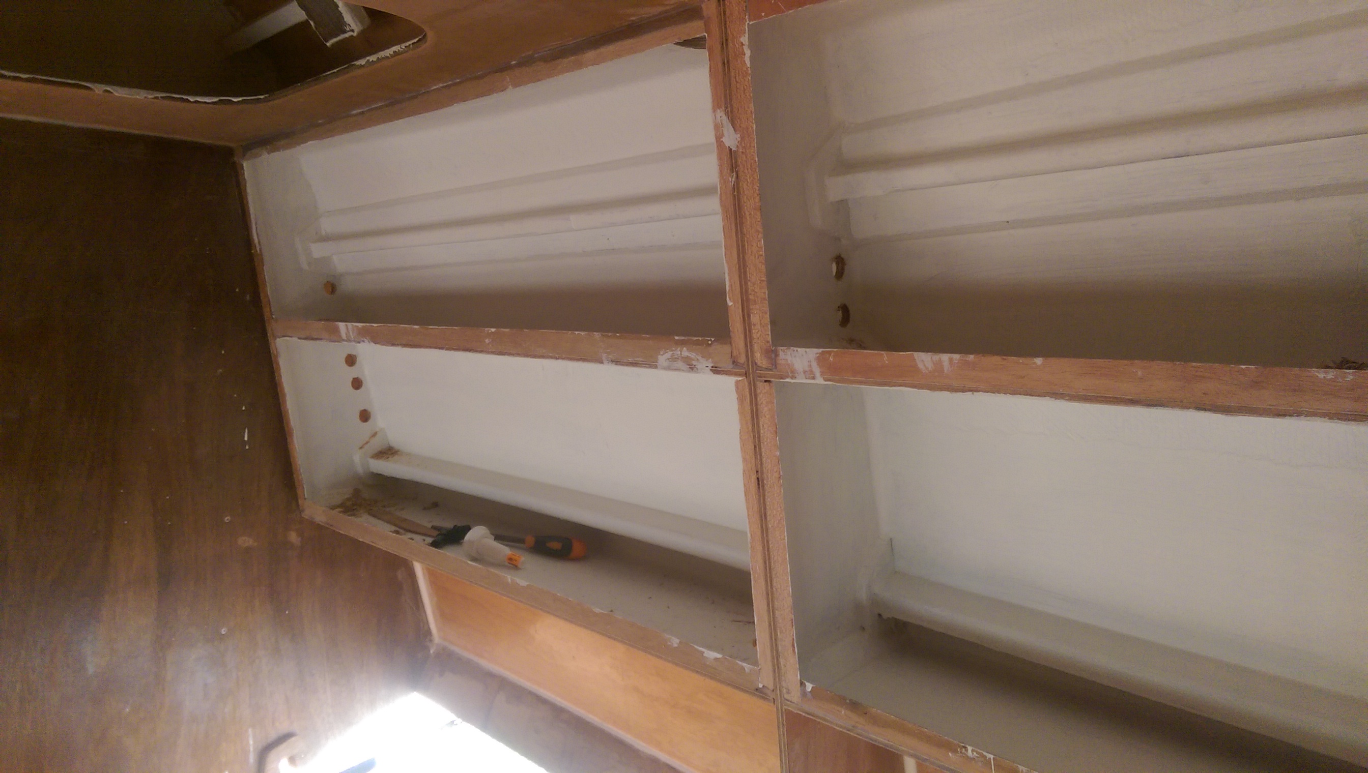
Didi 40 Cr settee shelves part painted and with wiring and plumbing holes cut.
The settee seats form the water tanks on both sides of the Didi 40 Cr so I have purchased the fill hose and cut the holes in the tank top for the fill and overflow lines. These are positioned in the corner of the shelves out of site so I will install the hoses onto the tanks before epoxying the seat back in place.

The inside of the settee backs has already been painted with three coats of Interprotect two pack epoxy primer. I masked off the areas that will be glued to the shelves and frames.
On Monday the last 650 kg of lead was poured into the bottom half of the fabricated steel fin section so the keel should now weigh the full 2000 kg. Also on Monday the contractors commenced constructing an awning over the hull. The awning will shade the middle seven metres of the hull to give me some protection while completing the deck and fit out. The posts for the awning have been purpose designed to support the load of the hull while we turn it over in slings. This is still a way off yet as the concrete footings have just been poured. In the meantime I have quarter berth shelves to fit and lots of painting to complete outside and inside.
Not much to show for a week of working on the project because it is all fiddly work fitting shelves and filleting and glassing them to the hull to make a strong box structure to support the chainplates. I have now glassed all the shelves in the photo to the hull on both sides of the boat. I need to fit timber cleats around the lip of each shelve to glue the settee backs in place. The settee backs are already cut to size and fitted but I intend to paint the inside of these storage spaces and the backsides of the settee plywood before gluing them in for good.

Plywood shelves to be glassed to the hull to form a box structure to support the chainplates
One other task completed was the “P” bracket support inside the hull. The inboard end of the bronze bracket is now encased in two substantial plywood blocks which are bolted together through a frame.
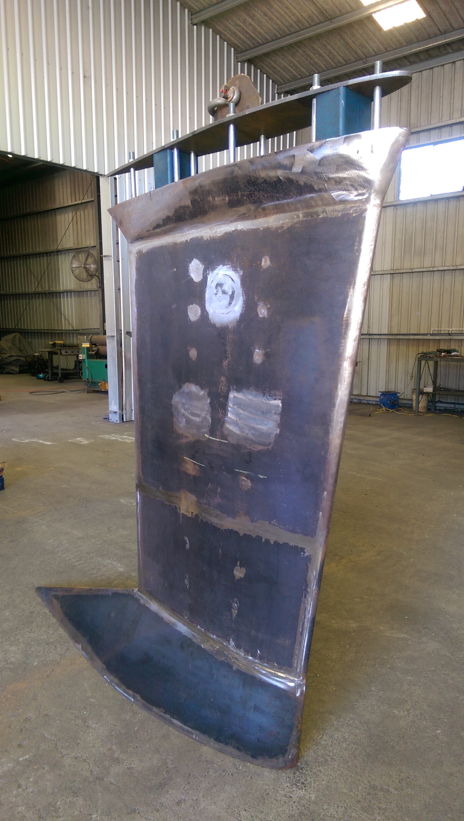
Thursday last week was devoted to supervising the assembly of the fin onto the bulb which is now filled with a tonne of lead. The laser level came in handy for getting the vertical alignment right and in six hours the fin was welded to the base ready for final structural welding around the perimeter. It looks large and as my daughter says “serious metal.”

Bulb and fin of our Didi 40 Cr keel joined ready for final structural welding.
The upper and lower rudder bearings are glassed to the hull so I fitted the first half of the rudder to the stock on the hull today. The size of the rudder came up in two separate discussions over the weekend so after the fit today I was able to stand back and get a good idea of the size. It looks pretty big to me. What to you think?
After a successful trial fit and final adjustment of the top of the rudder to the hull shape I bonded the two halves to the stock with a lot of glue.

Getting a feel for the rudder size on our Didi 4 Cr

The rudder half clamped to the rudder stock of our Didi 40 Cr for final adjustment.

With the two halves of the rudder of our Didi 40 Cr glued together the total weight is too heavy for me to handle so the next time the rudder stock will go into the hull will be just prior to launch.
In the week since my last post it would seem that not a lot has happened but a lot of fiddly jobs are going on under the hull. The rudder post bottom bearing is now well glassed into the hull and four plywood gussets have been glassed around it to make it strong enough for construction activity. After the hull is turned I will add five more layers of fibreglass to the plywood gussets which should make it very durable.
The stern tube through which the propeller shaft exits the boat is now glassed in and the propeller shaft is temporarily installed to ensure the everything stays straight while the glue sets. Similarly the P bracket which houses the bearing just in front of the propeller is glassed in place. I was not confident to do these tasks until Kevin came around for the afternoon and we could run a string line from the front of the engine centreline to the rear of the P bracked centreline to ensure all was aligned correctly.
While waiting for the glue on these tasks to set I have been back under the boat putting epoxy fillets between the frames and the hull skin and between the structural shelves and the hull skin. These frames and shelves can now be glassed to the hull for a very strong structure.
Not many of these tasks are worthy of a picture but I have been doing a bit more torture boarding and getting the finish on the hull closer to my target.

Using the sunlight to check how the hull fairing is progressing on our Didi 40 Cr.
I now have the Edson radial wheel drive which will be used to connect the autopilot drive to the rudder shaft and also the Hydralign feathering propeller so there is almost nothing to stop me installing the rudder stock and prop shaft bearings. I say almost nothing because JBC Yacht Engineering is turning down one end of my stern tube to match the internal diameter of my Radice shaft seal.
Other photos show the stern tube which I built up from 2.5 mm walls to 7 mm wall with epoxy glass and the epoxy glass housing for the lower bearing for the rudder stock. Both of these items have to be glassed into the hull. In the photo of the bearing housing you can see the Vesconite hi lube bearing already glassed in. In the space above the Vesconite I will install gland packing which will be held in place with the epoxy glass shaft follower that is almost completed.

Edson radial wheel drive with pin fitted for the autopilot arm.

Epoxy glass housing for the lower bearing on the rudder shaft.

Making a shaft follower to retain the gland packing on the lower bearing housing

Stern tube with 7 mm thick epoxy glass walls prior to turning the end for the Radice seal

15.5 inch Hydralign three bladed feathering propeller in the feathered position
Now that I have made the holes in the hull for the shaft log and P bracket it was time to double check the alignment of everything with the centre line of the hull. My home handyman Laser level is not bright enough to do be able to see the line in daylight but at dusk the lines light up on the hull.
I am very pleased with the check as the holes for the shaft log and P bracket were right on the centre line. The laser beam even went through the shaft log hole and shone onto the centre line mark for the engine and onto the bulkhead at the aft of the saloon.
From inside the hull I could look up through the keel bolt holes and see the laser beam passing across the centre line bolt holes.
Meanwhile the shaft is back at JBC Engineering having the three bladed feathering propeller fitted and the rudder stock is being fitted with the steering quadrant for the autopilot.

Using the laser level to check the alignment of the shaft log and P bracket on our Didi 40 Cr.

The laser beam shone through the shaft log onto the centre line of the engine bed.