Next Passion
Info on building of the next Passion
The timber that joins the cabin sides to the cabin top has been glued into notches in the frames and three additional laminated roof beams have been fitted. All of a sudden the cabin is taking shape. As a bonus I am slowly getting back some space in the garage as the five laminated roof beams move to the cabin top. The eight beams were laminated at the time I cut out the plywood frames. Three beams were needed to attach to the frames and I produced the additional five using the same jig.
The first frame in from the companionway sits on the fore and aft plywood frames that form the sides of the head and the quarter berth ante room. This beam had to be installed before the beam clamp at the cabin edge so that the beam clamp can fit in notches in the laminated cabin beams. The rest of the laminated frames have no structure under them and they can be lifted into place. Cutting the notches in the laminated beams is a work of art. The notches slope two ways and have rounded inside edges to match the routered edge of the beam clamp. Patience is important and my legs are sore from climbing in and out of the boat test fitting the notches to the clamps. A cutting blade on a multipurpose tool has been very useful for trimming the timber carefully to shape.
I have adjusted the laminated beam spacing slightly to suit the hatches available in Australia. They connect only to the beam clamp and one set of beams that run down to the carlins so moving them a little has no impact on other aspects of the structure.
Two more beams to go and I will start working on the sloping front of the cabin top.

The first cabin edge beam clamp installed on our Didi 40 Cr

Both cabin edge beam clamps and additional laminated cabin beams installed on our Didi 40 Cr
At times I feel that I am not building a yacht but am just making sawdust. With help from Kevin we made the triangular shaped carlins out of a 70 mm by 22 mm rectangular section. It took a while to work out a cutting sequence but once into production mode we cut three lengths which I subsequently scharf joined into two six metre lengths, one for each side of the deck. I had pre dressed the timber but each length had to have one last check for straightness and a few passes with the power planer. All of this produces sawdust. The worst job was trimming back the excess plywood on the inside edge of the deck. The internal curve is not too power plane friendly so I used a coarse disk on the angle grinder for the trimming. To be a good neighbour I covered the cabin with a tarpaulin to keep the dust contained and donned a face mask and goggles. For the final pass I went for a fine disk and am pretty pleased to have that job behind me. The vacuum cleaner was then used to collect all the dust from the deck before it blew away in the breeze. Elaine helped me clan up the sawdust from the circular saw bench and power planer and that filled half a good sized garbage bag.
The photos of the starboard side carlin give a good view of the side deck. The foredeck and part of the forward side deck is made from two layers of 6 mm ply while the rest of the side deck is one layer of 12 mm ply.

Starboard side carlin trial fitted to the deck. Note the triangular section.

View of the starboard side carlin from the bow
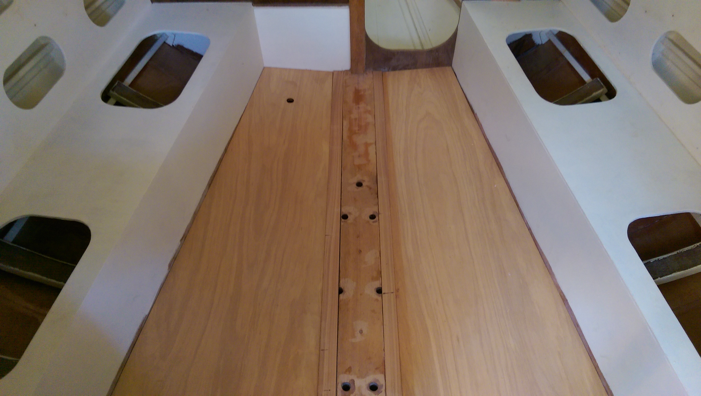
In my rush from task to task I had forgotten to show the photos of the wide stern of our Didi 40 Cr Wide Stern version now that the deck around the cockpit is fitted. This is about as good a photo as I can get for a while as there is not a good vantage point to photograph the side decks. Also today due to rain I worked inside the hull on the chart table. I was worried the the plywood for the lid was warped so I am pleased to report that after gluing on some trim it is now flat and ready to have the hinges fitted. The other useful job completed today was to trim the outer edge of the 12 mm plywood floor where it sits on the keel frames. These localized areas are trimmed back to 6 mm to give a large bearing area on the keel frames and to lessen the slope of the floor. Now the floor can be epoxy coated to protect it during the rest of the construction.

Our wide stern version of Dudley Dix’s Didi 40 Cr looks very modern

Today’s job was fitting reinforcing trim on the chart table lid

Chart table with lid in place ready to fit hinges
We had guest around for Easter Sunday dinner so I wanted to show the most progress for the least work. I had already put the floor in the settee area to make it a more usable work area. It was hard work stepping around the keel floors but now that there is a floor in place it is quite a useful work area. The most progress for the least work was to cut the plywood for the bunk tops. The forepeak was easy because I had already installed the edges that go around all the tricky framing and was left with just straight cuts. In the quarter berth area I had arranged bearers so that there was one rectangular piece and one tapered piece.
One of the benefits of having visitors around it that it prompted me to tidy up the boat building materials that had been sitting in the sun room for the past six months. Now we have a clean tidy sun room back to enjoy.
Today, Easter Monday, I set out the foredeck plywood and marked out the shape of the sloping area at the front of the cabin. That proved less difficult than I had expected so I had time to complete the fairing of the gunwhales all the way to the bow, cut out the first layer of most of the foredeck up to the anchor locker and add an extra 12mm plywood layer to the rear of the anchor locker. The optional anchor locker calls for two 12 mm doublers over the 9 mm frame plus a laminated beam checked int the gunwhales. The beam is laminated ready to install and the two 12 mm ply doublers are glued into place. The forward 12 mm doubler is difficult to fit after the hull skin is on and in hindsight I should have fitted this before the skin. The consequences were that I had a big of bogging to do with thickened epoxy to seal all the joins.
12 mm plywood floor provides a nice work area in our Didi 40 Cr

Quarter berth bunk tops in our Didi 40 Cr.

It was easier to install the vanity front on our Didi 40 Cr before the side deck was installed

The bunk tops in our Didi 40 Cr provide a very comfortable work platform for fitting the foredeck plywood

The first two 6 mm ply layer on the foredeck of our Didi 40 Cr are cut and ready to glue in place.
There are many options for joining the adjacent edges of plywood sheets and Dudley’s covers the options pretty comprehensively. The choice of join depends on many factors and I have used butt joins with plywood backing, taped joins, flush taped joins and scarph joins in various locations. Even the butt joins with plywood backing will have flush tape on the other surface if they are exposed or under load.
Today I prepared deck joins for both scarph joins and for plywood backed butt joins. The scarph joins are on the aft deck where it was convenient to do the scarph in situ. The plywood backed butt joins will be used to join the bridge deck to the two sides and for some of the joining panels along the deck where the joins are quite close to frames. In these cased one edge of the plywood backing piece will be fitted against the frame and the other edge will be beveled 45 degrees.

Preparing the scarph join for the aft deck around the gas bottle locker

Plywood ready for gluing around the gas bottle locker

A plywood backing piece ready for a butt join across the bridge deck

Close up of the full 45 degree bevel on the edges of the plywood butt join backing piece

Scarph join ready for gluing on the starboard quarter of our Didi 40 Cr Wide Stern version.
All the jobs on my list for today were completed with great assistance from Kevin. The splices in the stringers were cleaned up, the deck clamp stringers were cut to the correct bevel for the deck plywood and all the stringers were fitted from stern to stem. All the remaining cleats for the deck were glued in place and in the warm conditions the glue soon cured. We installed the diesel tank in its final position and adjusted the deck beam above the gas locker to give more clearance for the gas bottles at the stern of the locker. I still have to install cleats along the top edge of the stainless steel tank to secure it in position and add a 6 mm plywood protective panel across the top.
The two of us sharing the load of carrying the 12 mm plywood sheets made the task of fitting and cutting the deck plywood much easier. Tonight most of the deck around the cockpit is covered in plywood which is temporarily screwed into place. I will wait for a cool change before attempting to glue these in place as there is a lot of glue to place before the glue surfaces can be fastened together. I will probably pre measure some small batches and only add the part B to the part A as each batch is completed. Otherwise the heat generated in a large batch would cure the mix before it could be placed.
I think I will cut out most of the 12 mm deck panels and the 12 mm plywood doublers before starting the gluing. It will be easier to mark the shape of the doublers off the stringers before the deck is fitted.

Stainless steel fuel tank in position

12 mm plywood deck panels temporarily screwed into position. Note the gloss on the epoxy glass floor of the cockpit.

The gas locker on our Didi 40 Cr Wide Stern version. Just the two pieces of plywood were needed to form up an air tight locker. I will move the stringer out on the transom about 30 mm to give clearance for the gas bottles at the back as well as the front of the locker.

The underside of the gas locker on our Didi 40 Cr Wide Stern before final fit and structural epoxy adhesive.
I am pleased with the gas and fuel locker on our Didi 40 Cr Wide Stern version. The enclosure was completed with just two pieces of 12 mm plywood and as well as enclosing the gas bottles in an air tight locker they provide additional support for the wide T shaped cockpit. I will glass the bottom of the locker both to protect the timber from the metal gas bottles and to bond the 12 mm ply to the frames, cockpit side and hull side. After a final fit today I ground off the two pack epoxy primer to give good adhesion for the plywood and later the glass on the bottom which will be turned up onto the frames. I then glued the 12 mm plywood in with thickened structural epoxy and in a few hours the locker was completed. There is one post completion job to do and that is relocate the deck stringer above the gas locker to give a few more millimetres of clearance. I will run the stinger parallel to the cockpit top so that I can put gas bottles in both ends of the locker without having to move one out to replace the second one.
I am still harbouring ambitions to get the 12 mm plywood on the deck around the cockpit area. That means fitting all the deck stringers since the plywood will extend into the area adjacent to the cabin. Both the 35 mm deck stringers and the 44 mm beam clamp that sit under the carlins need to be fitted. These are long lengths of timber so today was spend planing and routering edges and making splice joins in the long lengths. These are curing as I write and by the morning they will be ready to drop into place.
I must remember to drop the fuel tank into position as it will be easier before the deck goes on. Mine is a stainless steel one located in the very front of the locker just behind the wet locker. There are a couple of small cleats that need to be added so I might make an early start so the glue on these is cured in time.
And a final reminder to myself I need to clamp straight edges to all the frames so that the stringers will hold them straight. Yes even at this stage the unsupported edges of the frames can still move around and this will be the last chance to keep them straight.

Splice joins on the stringers for our Didi 40 Cr clamped together on a straight piece of LVL

Long stingers spliced together ready for final fit to the deck frames.
Mondays seem to be the days I feel that I make progress on the construction of our Didi 40 Cr. I was thinking today that if I had all Mondays the boat would be completed sooner. Perhaps the weekend sailing the Laser clears the head But today I made an early and measured start with some detailed tasks and as the day progressed installed more and more deck cleats and reinforcement. It did help that the timber had all been pre cut last week and all that was needed today was trimming to size and routering edges where required. By the end of the day the two ends of the large deck locker had been glued and cured ready to take the water seals, all the deck cleats were completed and the gas bottle hatch marked up. It was handy having a spare gas bottle to use to check the size of the lid required and the depth of the locker needed. As a final dirty job for the day I sanded the rudder stock bottom bearing support area ready for heavy layers of glass and epoxy possible as soon as tomorrow. Hopefully all the thinking is finished in this area and I can move into production mode. The thought of getting some of the deck installed is motivating me but can I do it by Friday?

Installing deck cleats on our Didi 40 Cr using a straight edge and clamps so that the edge of the plywood cures as straight as possible

Plywood reinforcement has been added to the frames at the ends of the deck locker hatch. Because of the T shaped cockpit the back edge of the locker needs considerable reinforcement and I settled on three additional layers of ply for a total of 48 mm.

Perhaps tomorrow’s job is heavy glassing around the rudder stock bottom bearing. The heavy hardwood doubles on both sides of the keel are impressive reinforcement so the extra glass will make it super strong. I am glad I did this work with the hull upside down as the area is mighty cramped now it is right way up.
Today Elaine and I moved Passion from the mooring in Valentia Street Woolwich to our new mooring at Greenwich not far from the Greenwich Flying Squadron where the dinghy is now stored.
We had a pleasant lunch in the shade of the trees at Woolwich while watching our mooring contractor attend to a large yacht in Woodford Bay. As soon as the mooring barge left Woodford Bay we raced to Passion’s mooring on the other side of the peninsular at Valentia street so I could motor Passion to Greenwich towing the tender. At Greenwich I picked up a spare mooring and waited for our mooring from Valentia Street to be relocated. It was warm down below as I used the spare time to delete spurious way points from the chart plotter and enter our new mooring location.

Looking back to Cockatoo Island from Passion’s new mooring at Greenwich

Looking North to Greenwich Flying Squadron from Passion’s new mooring in Greenwich
The row to Greenwich Flying Squadron is about 400 metres and it took six minutes to reach the club. After ten years stored on the rocks at Woolwich the tender needed a clean with the high pressure machine which Elaine had driven around from Woolwich. An hour later the dinghy was cleaned and in the allocated rack ready for next Wednesday.
As a result of the time taken on Passion very little was achieved on the new build. I did cut out the side of the cockpit where the anchor locker is located and made a start on reinforcing the frames either side of the locker.

Our Didi 40 Cr just after turning. The chain blocks and slings are back in storage and the cockpit is now covered with epoxy glass and all the deck beams in this area are fitted.

The details at the front of or wide stern Didi 40 Cr. A laminated deck beam had been fitted across the front of the cockpit. It is notched into the side of the wet locker and goes all the way to the side locker in the quarter berth.
After the excitement of the hull turning ceremony ten days ago the euphoria has gone and now the hard grind to the finish has started. The first task was to protect the raw plywood on the deck and boarding platform. These now have a heavy layer of glass and two thick coats of epoxy so the timber is sealed and the surface is shiny smooth. The bare plywood in the base of the anchor locker also got the heavy glass and epoxy treatment but in this case it was two layers of glass over the bottom, one on the sides and doubled over the corners.
With that out of the way I spent nine hours on Monday planing away the surplus timber from the gunwhales and fairing up the tops of the frames. Tuesday I laminated up a 32 by 32 mm beam to go across the deck just in front of the cockpit well. This joins the deck and cockpit and is also the support for the mainsheet traveller for those who put the track in this position. Because the beam is visible in the quarter berth the bottom corners had to be routered before installation. Today I installed most of the deck beams for the cockpit area and again the beams had to be routered prior to installation.
At the front end of the boat I have cut out the second 12 mm plywood panel to reinforce the back of the anchor locker and also laminated up a 25 mm by 42 mm beam to be notched into the gunwhales. This structure will take the anchor load from a Samson post or an electric winch and is also suitable to take the load of an inner forestay if fitted. I have already installed plywood doublers 100 mm wide along the bottom edge of the gunwhale to take an external bowsprit and will put plywood doublers down both sides of the narrow deck around the anchor well.
Ahead I have to form up the locker hatch area before I can deck that side. It would be unfortunate to forget to put the hatch in and find there was no way in or out. It seems that completing the deck from the stern first is a good safety measure as it creates a stable strong working platform for the next stage.

Morning tea mid way through the turning party for our Didi 40 Cr

Didi 40 Cr at the tipping point in the hull turnover process

Didi 40 Cr well on the way to being right side up

Now the Didi 40 Cr just needs to lowered onto the cradle

The turnover party crew

Early progress on turning our Didi 40 Cr
The turn over of our Didi 40 Cr hull went according to plan today. I was confident enough to invite people to come and help and watch but nervous nevertheless. We started the job right on 10 am and used the chain blocks to lift one side of the hull. The rope wrapped four time around the hull was meant to turn the boat but it kept slipping on the shiny painted surface so we used the chain plate frames as attachment points for the turning ropes. Once we had a firm pull on the hull it turned readily in the slings. Soon our main concern was preventing it toppling over once the centre of gravity went over the top. Again rope attached to the chain plate frames was used as a steady as the hull slipped slowly in the slings into the upright position.
Once the hull was level it was time for a break and to celebrate with a sip of champagne.
Tonight there are tarpaulins over the bow and stern where the hull protrudes from under the awning.
Today I liberated the DIdi 40 Cr hull from the building frame in preparation for turning it on Monday. The task went to plan and I applied just enough tension on the chain blocks that connected to the slings holding the hull so that the hull did not slip lower on the frame. As I progressed from stern to bow I had released eight of the twelve supports before the supports started to lift away from the reference marks.
Once all the supports were released I raised the hull high enough to fit the rear cradle to the building frame. That will be completed tomorrow in time for the turn on Monday.
Another milestone of sorts was completing the wet sanding of the International Interprotect two pack epoxy primer on the hull below the water line. I figured it was easier to sand while the hull was upside down. The environmental dust that had settled on the hull was a good sanding guide and the more I sanded the cleaner and more slippery the hull became. For the last section today I was worried about sliding off the hull and thinking of the song “Slip Sliding Away.” It is corny I know but one of the names I had thought about for the boat was “Destination” and the song goes “The nearer your destination the more you go slip sliding away”

A slippery looking hull when washed down to keep the dust from annoying the neighbours

Yes it is starting to lift off the building frame.

Just a one hand pull on the one tonne chain block to lift the stern of our Didi 40 Cr

The aft cradle is positioned ready for level measurement and securing to the building frame.
Cannot resist a photo of the access stairs now that I have a second coat of clear epoxy on them. Also a close up of the quality of the plywood used in the stairs and also in the hull.
Another alteration I have installed is 12 mm plywood reinforcement over the keel in two places where there is a splice join. Dudley’s plan already has plywood across the centre line join down the keel on the outside of the hull. This provides considerable cross grain strength to the keel. I have added the 12 mm plywood to give cross grain strength in the inside of the keel as well as stiffness along the section. So effectively there is a sandwich construction with ply on both sides of the meranti keel. Each 12 mm piece of plywood weights approx 2 kg so for 4 kg additional weight low down on the keel I get a lot of insurance. I added these because the meranti backbone has a massive amount of cross grain reinforcement in the keel floor area and then nothing extra in the quite wide spans between the frames fore and aft of the keel.

No worries about cross grain strength in the keel floor area. The laminated frames are 110 mm wide where they cross the meranti backbone

An interior layer of 12 mm plywood for cross grain strength for the keel (backbone) of our Didi 40 Cr

12 mm plywood reinforcement across the keel at a splice join in the meranti backbone.

The companionway stairs for our Didi 40 Cr already looking good with just two coats of clear epoxy. More to come.

A close up of the 24 mm thick plywood stairs construction. This is the same plywood used in the hull of our Didi 40 Cr in 12 mm thickness.
We have another short week for boat building so I am doing fill in jobs. Today I made the access ladder which will be very handy once the hull is turned and another job off the list. Yesterday I skipped sailing the Laser and glued up some 12 mm plywood to make 24 mm plywood planks for the steps and rails. It took all of today to shape the components and glue them together. The photo shows some temporary cross bracing to keep the structure square until the glue cures.
The plans for the Didi 40 Cr comprise the original plans for the Didi 38 plus some additional frame details for the extended Didi 40 Cr. The ladder is further aft in the Didi 40 Cr so some adjustment to the profile shown in the Didi 38 was needed. I also measured up the stairs on our Sun Odyssey 37, Passion, and was surprised to find that the tread depth and height are exactly the same. Passion’s treads are made from 24 mm ply so I thought I would do the same on the new boat.
I had considered installing the water heater under the stairs but there is not enough space. The bottom of the wet locker in the head is however the right size and it will make the bottom of the locker a similar depth to Passion.
Most days I spend a couple of hours sanding the roller pattern off the last coat of Interprotect. It has cured to a very hard surface so I should have done this job within three days of the last coat.

The access ladder for our Didi 40 Cr.
I missed my self imposed deadline of the end of January to turn the hull partly due to wet weather but more to do with family matters which will keep us occupied this week. There is no rush to turn the hull and leave the inside exposed to the elements and I have a lot of jobs that can still be completed with the hull upside down. Today was a big sanding and painting day and now the huge aft locker is coated with two coats of white epoxy primer on top of the two or three coats of clear epoxy. Not only is the timber more protected but the interior is lightened up considerably.
I have rigged up one of the slings to lift the hull and used the two tonne chain block to take up the load. It is so tempting to fit the other sling and lift the hull but I will be patient.

A view across the area where the rudder stock will go. The steering quadrant for the autopilot will go on the rudder stock in this area.

You can see how the widened aft cockpit reduces the volume of the locker but there is still plenty of volume and enough full length area for the long items.

A view through the companionway. I will need the ladder soon to get into and out of the hull.